20-01
Formula FSAE: EV Accumulator Enclosure
Overview
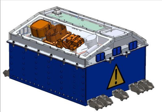
An aluminum accumulator enclosure for Olin Electric Motorsports, developed using SolidWorks Sheet Metal, structural fastener calculations and coordination across mechanical and electrical subteams.
Objective
The previous Olin Electric Motorsports accumulator enclosure used Garolite (G-10 composite). Updated FSAE rules required high-temperature mechanical testing for composite enclosures, which had been permitted under the earlier rules.
Olin did not have the equipment or facilities for the required elevated-temperature testing. The team's priority was endurance reliability rather than weight reduction, so aluminum provided a practical alternative to G-10.
As the Accumulator Engineer, I was responsible for redesigning the enclosure to meet FSAE rules, withstand 60 °C, protect the cells mechanically, segment the pack safely, manage heat, and remain both waterproof and serviceable. All while staying backward compatible with the previous chassis and mounting system.
Engineering constraints
| Parameter | Requirement, context or design choice |
|---|---|
| Required temperature capability | 60 °C |
| Floor / walls | 3.2 mm / 2.3 mm aluminum, per FSAE Rule F.10.2 |
| False floor | 1" insulated standoffs |
| Divider attachment | 1-inch welds |
| Pack / segment configuration | 102s4p / 17s4p |
| Maximum pack voltage | 428.4 V |
| Integration | Existing chassis and mounts; segment isolation, waterproofing and serviceability |
My contributions
I began by translating the FSAE rulebook into a clear list of design requirements, including minimum wall and floor thicknesses, segment isolation requirements, positive locking mechanisms, allowable airflow openings, and the approved materials (steel, aluminum, or tested composites). After comparing manufacturing complexity and testing requirements, I decided to move forward with an all-aluminum enclosure.
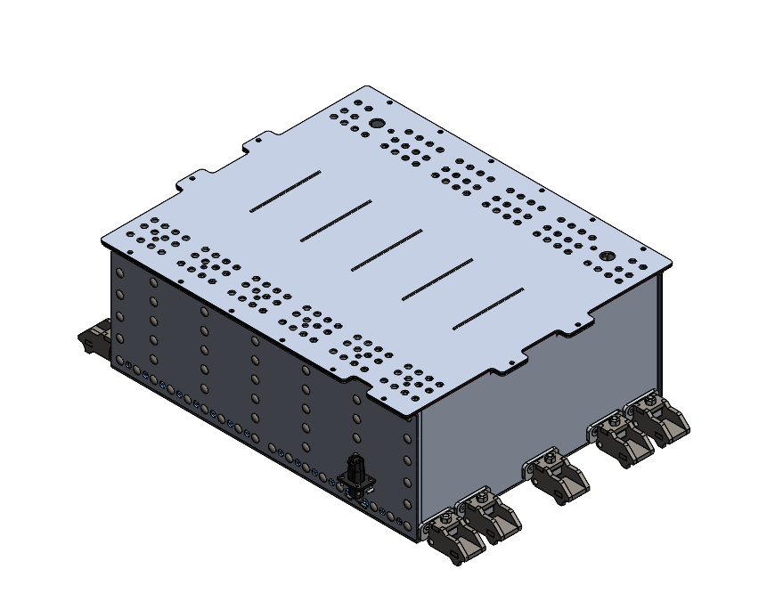
Because the new design needed to remain compatible with both the current and previous chassis, I built the enclosure using parametric equations in SolidWorks, allowing fast iteration and dimensional updates. My background in aircraft maintenance strongly influenced my fastening strategy—rivets are reliable, serviceable, and ideal for sheet-metal construction. They also eliminated the alignment issues caused by the old epoxy-bonded L-brackets. I performed hand calculations to verify rivet pitch, shear strength, bearing strength, and spacing for our chosen aluminum thicknesses.
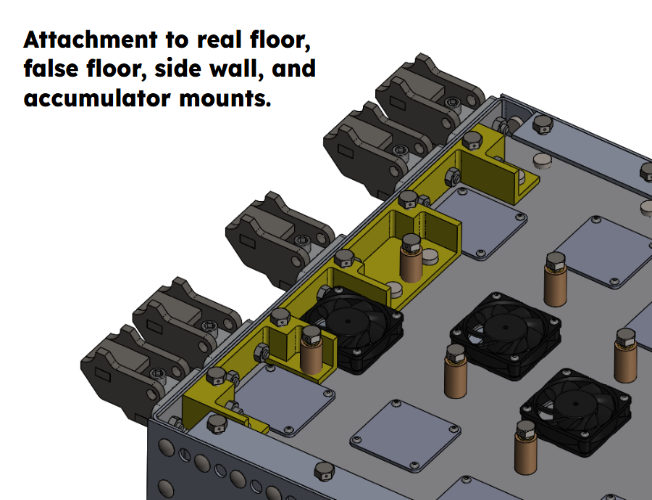
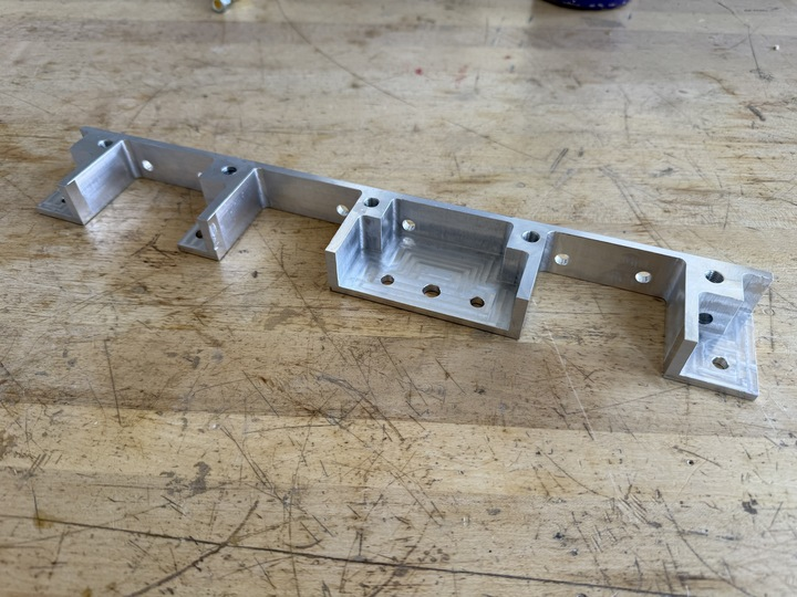
This work required continuous collaboration with multiple subteams. I coordinated with the cooling engineer to integrate the pendulum mounted fans, the service section designer to fit the top access panel, and the mounting engineer to confirm chassis clearances and load paths.
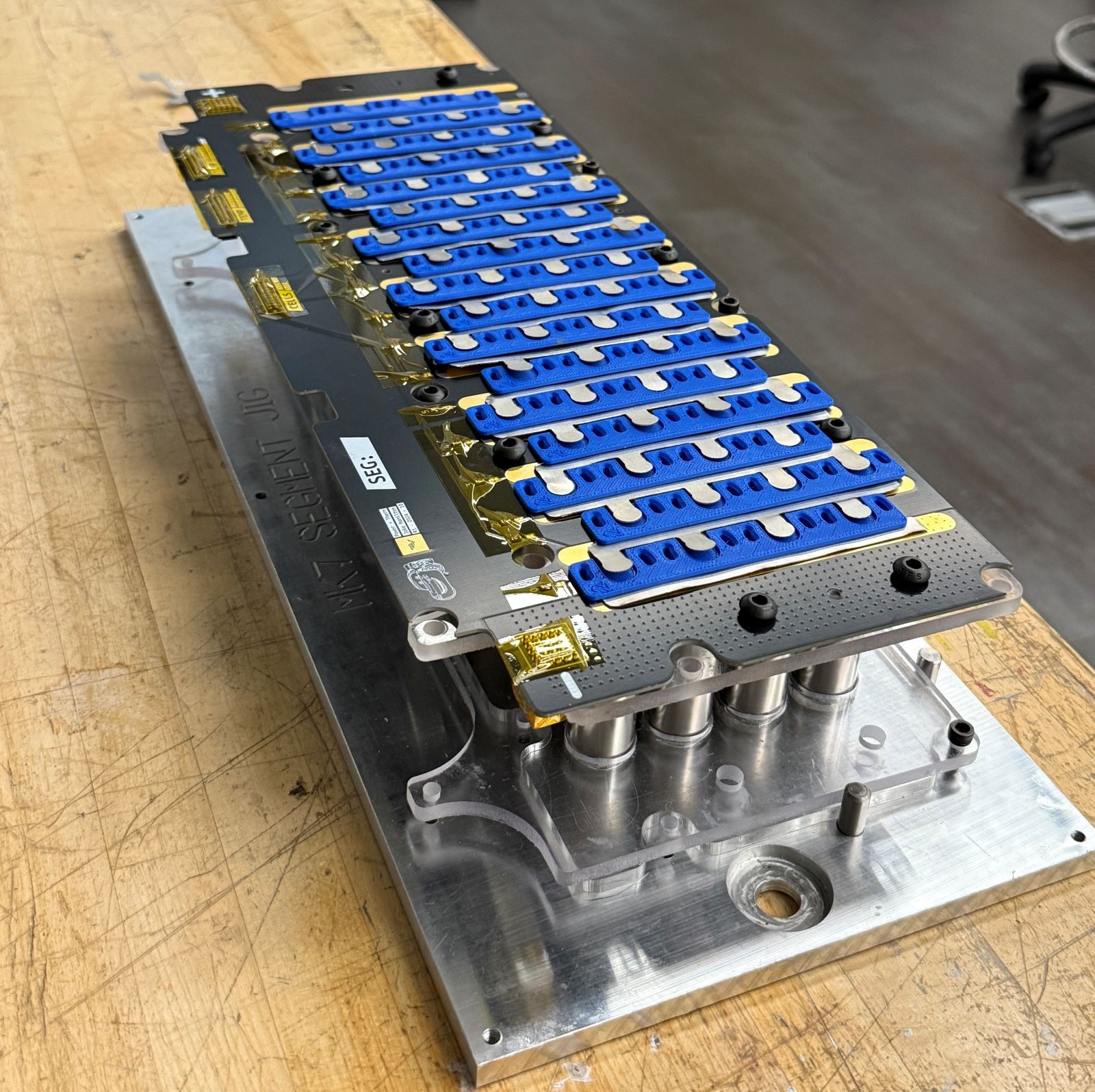
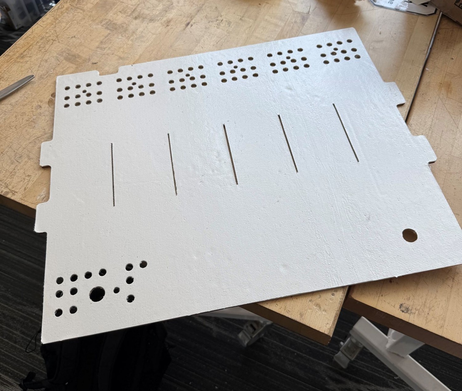
I also added rule compliant airflow holes between segments to improve cooling consistency.
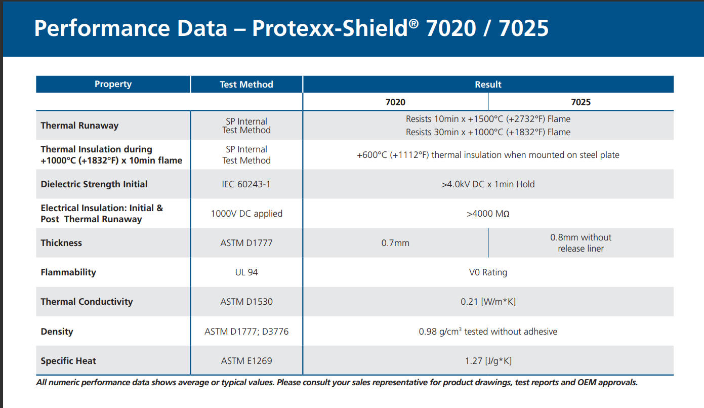
Because our pack operates at 428.4 V (102s4p), electrical insulation was critical. After researching multiple options, I selected Protexx-Shield® 7020 as our internal dielectric liner to prevent the battery segments from contacting the aluminum walls.
I researched multiple dielectric coatings and selected Protexx-Shield® 7020 / 7025 for internal isolation.
Design and fabrication process
The enclosure was modeled using SolidWorks Sheet Metal and included:
- 3.2 mm aluminum floor and 2.3 mm walls per FSAE Rule F.10.2
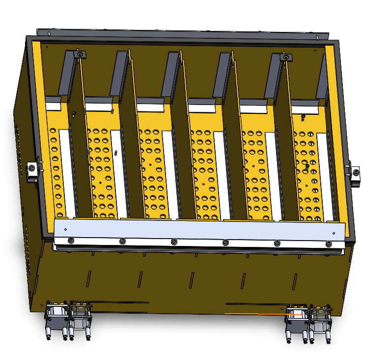
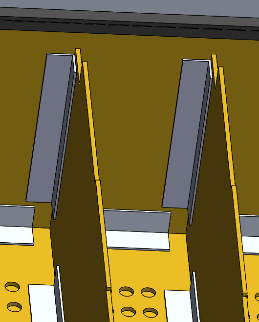
- Internal divider walls, fully surrounding each accumulator segment
- A false floor on 1" insulated standoffs for airflow and wiring
- Built-in wall flanges replacing L-brackets for a stronger, simpler assembly
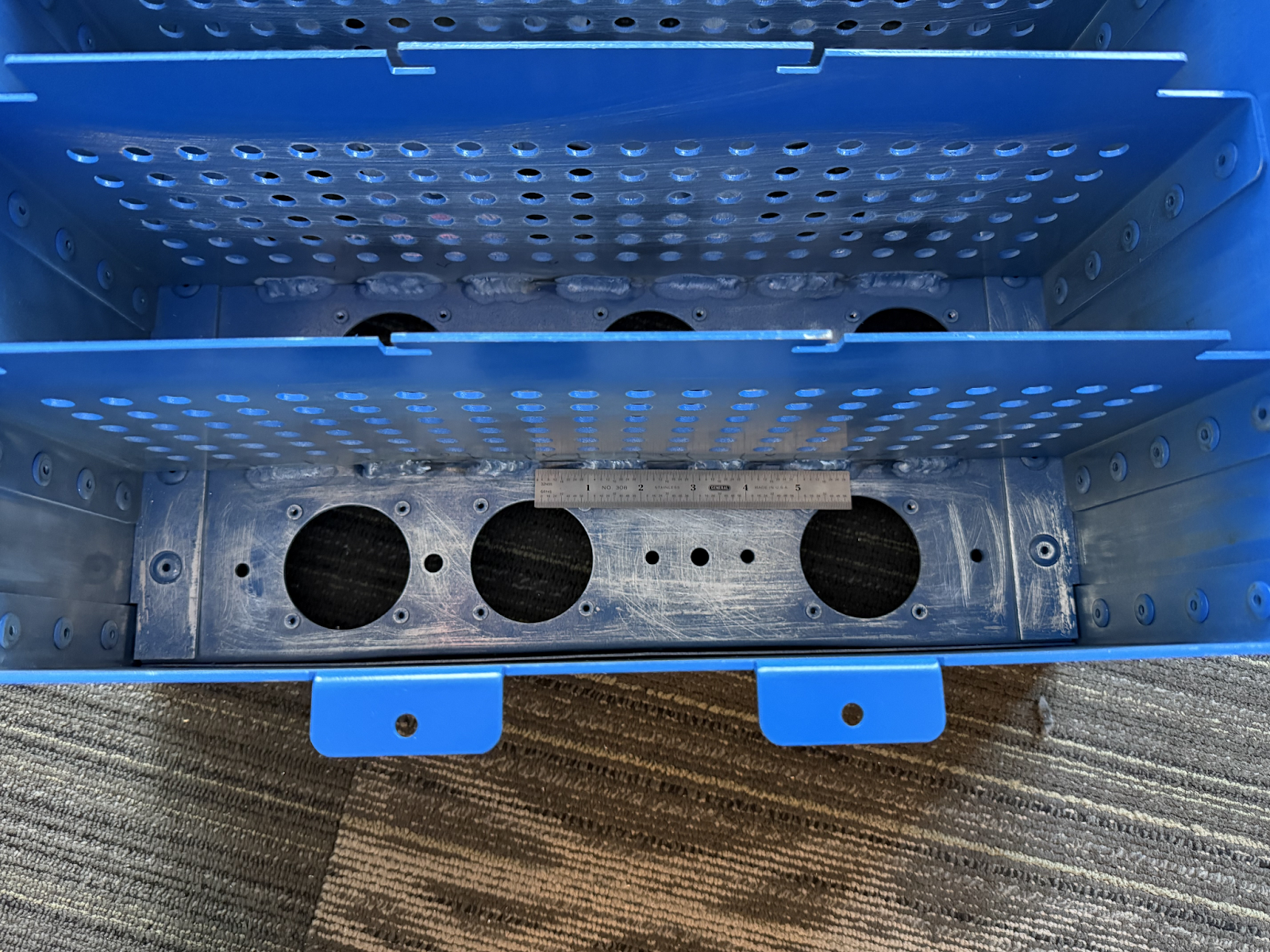
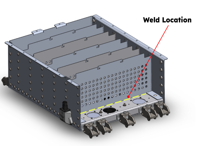
During our SES review, it was discovered that the divider walls were not mechanically attached to the floor. This is an issue for both structural rigidity and rule compliance. To resolve this, we added 1-inch welds along the base of each wall, creating a continuous, robust connection without interfering with battery segment spacing.
Results
The completed aluminum enclosure uses riveted sheet-metal construction and welded divider-wall attachments. It incorporates consistent rivet spacing, proper edge distances and structural segmentation, with each battery module in its own compartment. The design was manufacturable with the team's in-house capabilities.
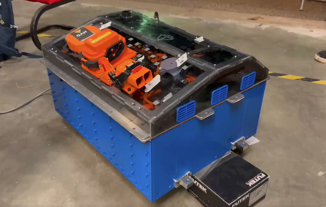
The new flanged wall architecture eliminated the alignment issues inherent in the old L-bracket system and reduced overall part count, improving both assembly speed and structural rigidity. The false floor created a dedicated layer for airflow while maintaining electrical isolation through insulated standoffs. The use of Protexx-Shield® provided electrical and environmental protection, resulting in a sealed, electrically isolated housing capable of operating safely.
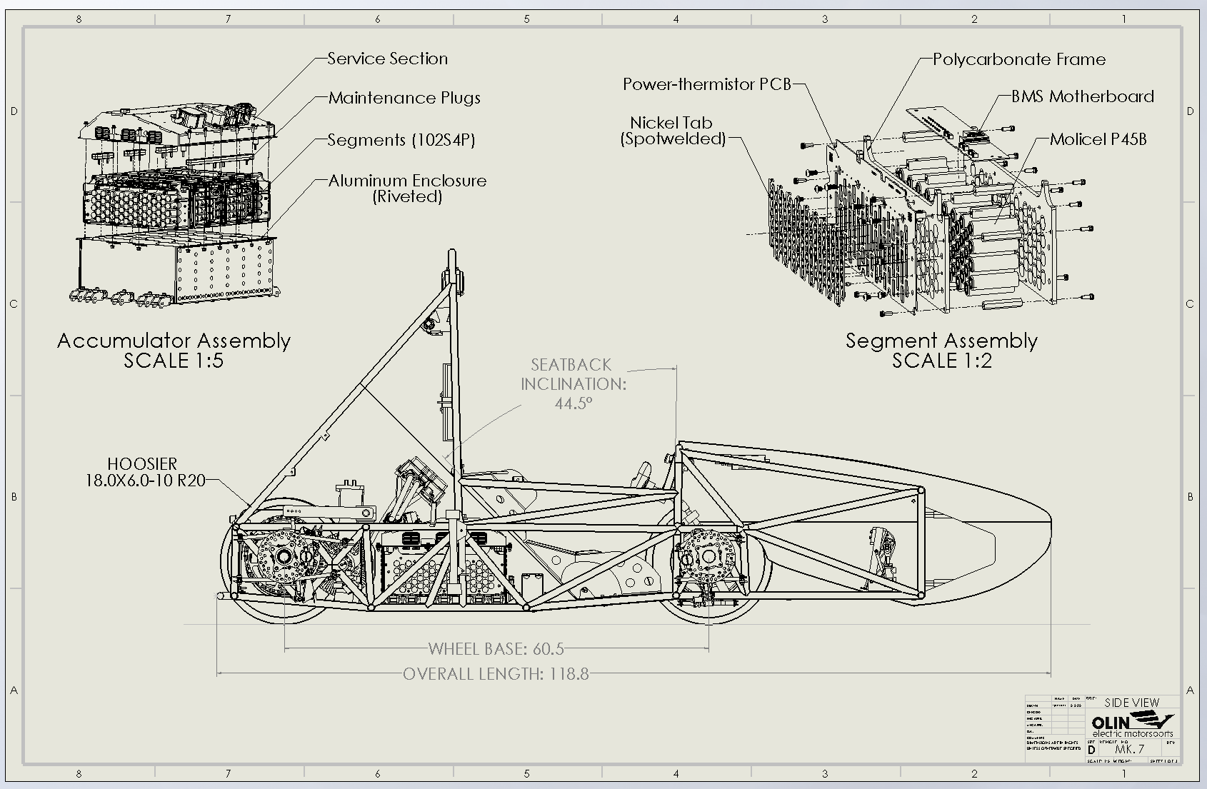
During the final design review, the enclosure was validated for manufacturability, accessibility, and inspection readiness. Welded divider walls resolved SES review feedback and achieved full compliance with segment isolation requirements. The finalized CAD model and documentation remain stored in the team’s PDM vault as an approved baseline enclosure for the next generation Olin Electric Motorsports vehicle.
I also had the opportunity to attend the FSAE competition in Brooklyn, Michigan, where our team successfully passed the official Accumulator Inspection, confirming the enclosure’s compliance and build quality under real competition standards.
Skills and tools
SolidWorks Sheet Metal, Design for FSAE Compliance, Structural Fastener Sizing (Rivets), High-Voltage Packaging, Requirements Tracking, Design Reviews & Documentation, Collaboration with ME + EE subteams