20-08
Breath Detection Sensor - Thermistor + Op-Amp Band-Pass System
Overview
A thermistor-based breath-detection circuit combining analog amplification, filtering and signal analysis.
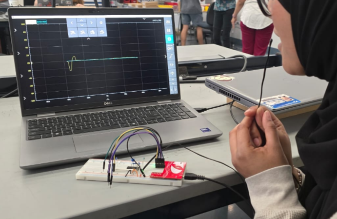
Objective
Our goal was to design a system capable of detecting human breaths using a temperature based sensor while minimizing noise, drift, and environmental interference. The circuit needed to reliably convert thermistor resistance changes into a measurable voltage signal that could be amplified, filtered, and analyzed to calculate breaths per minute (BPM).
Engineering constraints
Convert thermistor resistance changes into a measurable voltage for amplification, filtering and breath counting, while reducing noise, temperature drift and environmental interference.
My contributions
I produced 13 breaths over 75 seconds during the measurement, corresponding to approximately 10.4 breaths per minute.
Design and fabrication process
Sensor
We used a thermistor to detect the warm air produced by each exhale. As temperature increased, the thermistor’s resistance decreased, creating small voltage changes in the circuit.
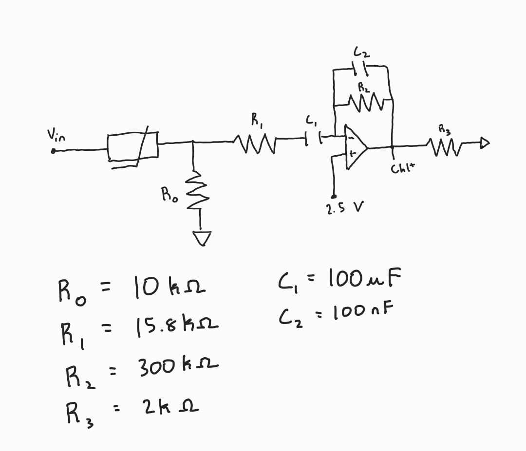
Circuit Design
The system consisted of:
- A voltage divider to convert thermistor resistance → voltage
- An op-amp amplifier with a gain of 151
- A two-stage filter for signal conditioning
Amplifier
The amplifier boosts the small voltage changes produced by the thermistor.
The gain is set by the resistor ratio:
Gain = 1 + (R2 / R3)
R2 = 300 kΩ
R3 = 2 kΩ
Therefore:
Gain = 1 + (300 kΩ / 2 kΩ) = 151
Filter component values
| Stage | Resistance | Capacitance | Cutoff frequency |
|---|---|---|---|
| High-pass | R0 = 10 kΩ | C1 = 100 µF | ≈ 0.16 Hz |
| Low-pass | R1 = 15.8 kΩ | C2 = 100 nF | ≈ 100 Hz |
Conversion of Raw Signal
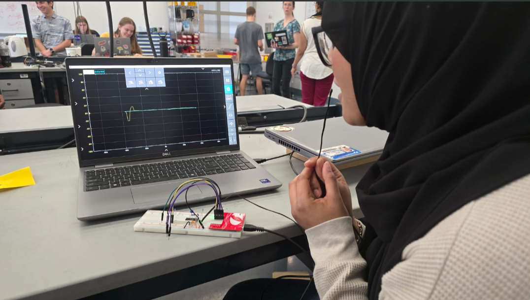
Every exhale produced a temperature spike, reducing the thermistor’s resistance. The voltage divider converted this into a measurable voltage change. The amplifier boosted the signal, and the filter conditioned the signal. Peaks in the filtered signal corresponded to individual breaths and were counted to compute BPM.
Results
Breathing Measurement
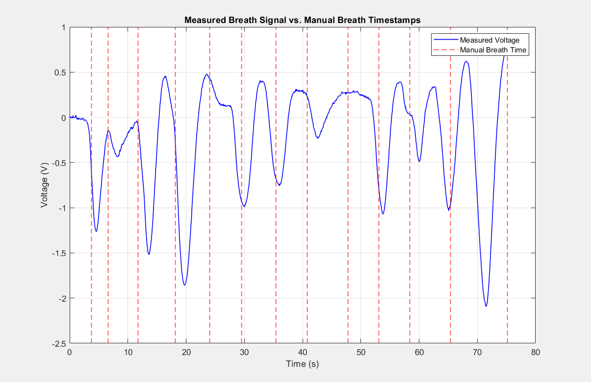
I produced 13 breaths over 75 seconds, giving a measured rate of approximately 10.4 breaths per minute.
The oscilloscope output showed clean, distinct peaks, confirming that the sensor, amplifier, and filter chain successfully detected each breath.
Bode Plot
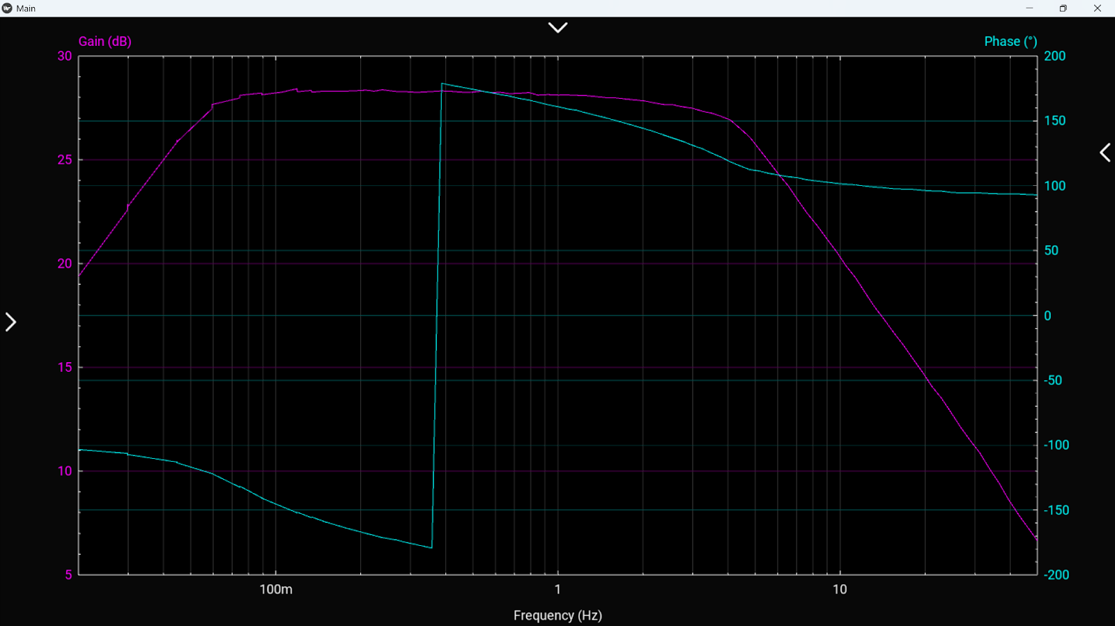
The amplifier gain was 151. The frequency-response plot is shown above; component values and cutoff frequencies are listed in the process section.
The project successfully demonstrated how a temperature based sensor, combined with analog filtering and amplification, can reliably detect human respiration.
We achieved:
- Clean peak separation
- Accurate BPM calculation
- Stable signal processing
This project strengthened my understanding of analog circuits, instrumentation design, and practical signal conditioning for real world measurement systems.
Skills and tools
Circuit Design, Thermistor Integration, Op-Amp Amplifier Design, Band-Pass Filter Design, Signal Processing, MATLAB/Data Analysis, Bode Plot Interpretation